

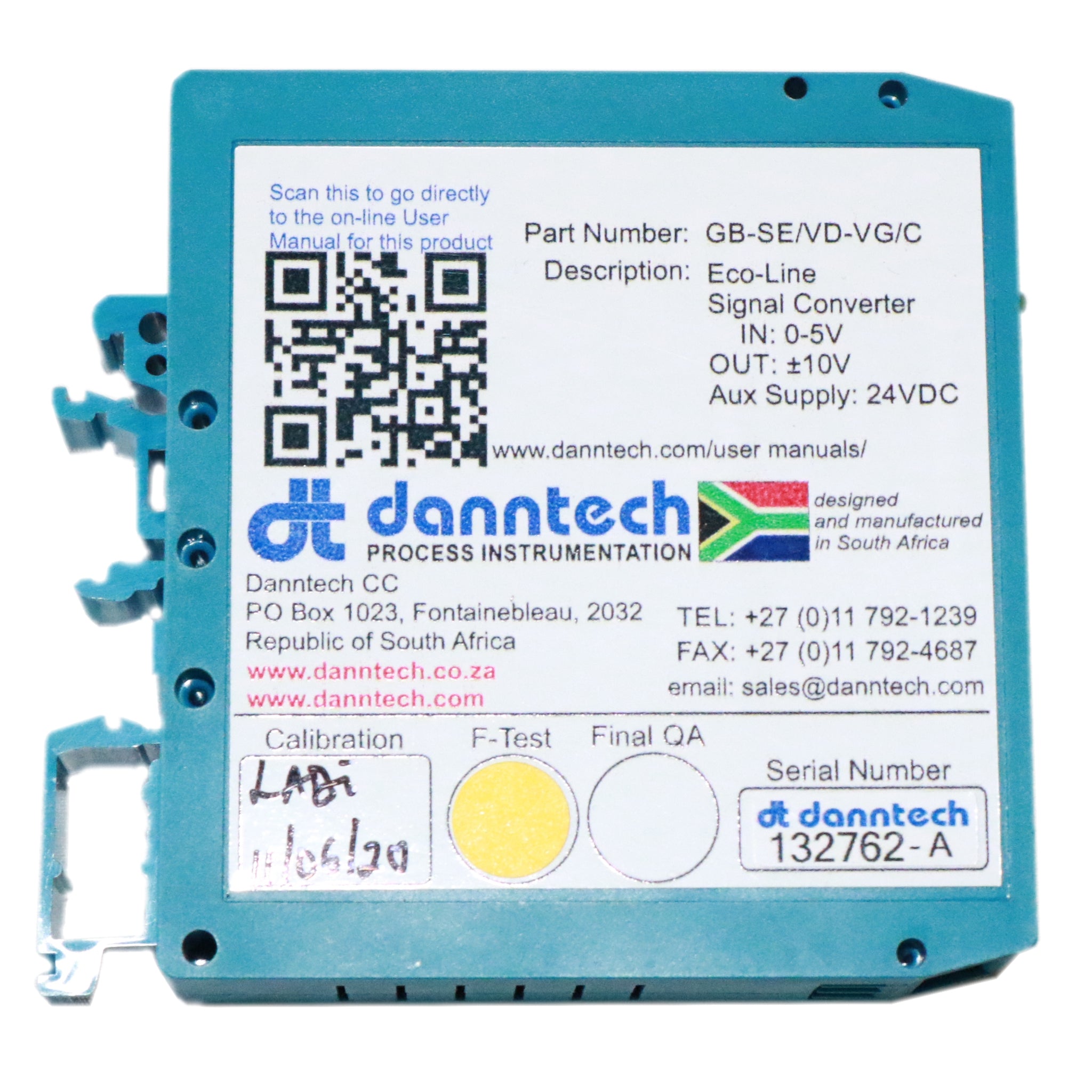


This product is a custom version of the Eco-Line Signal Converter. These are made to your specifications and take longer to manufacture and test.
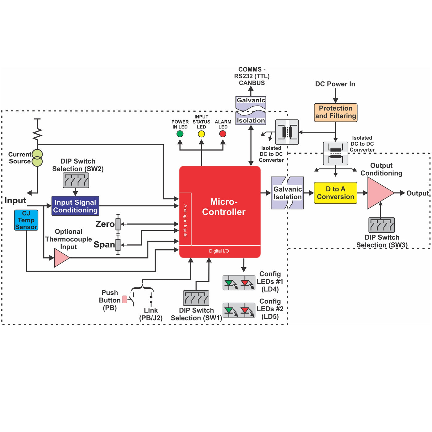
The Eco-Line range of signal converters has been designed using a low-cost, powerful microprocessor which enables us to offer flexibility, reliability and accuracy at a really good price in a small package.
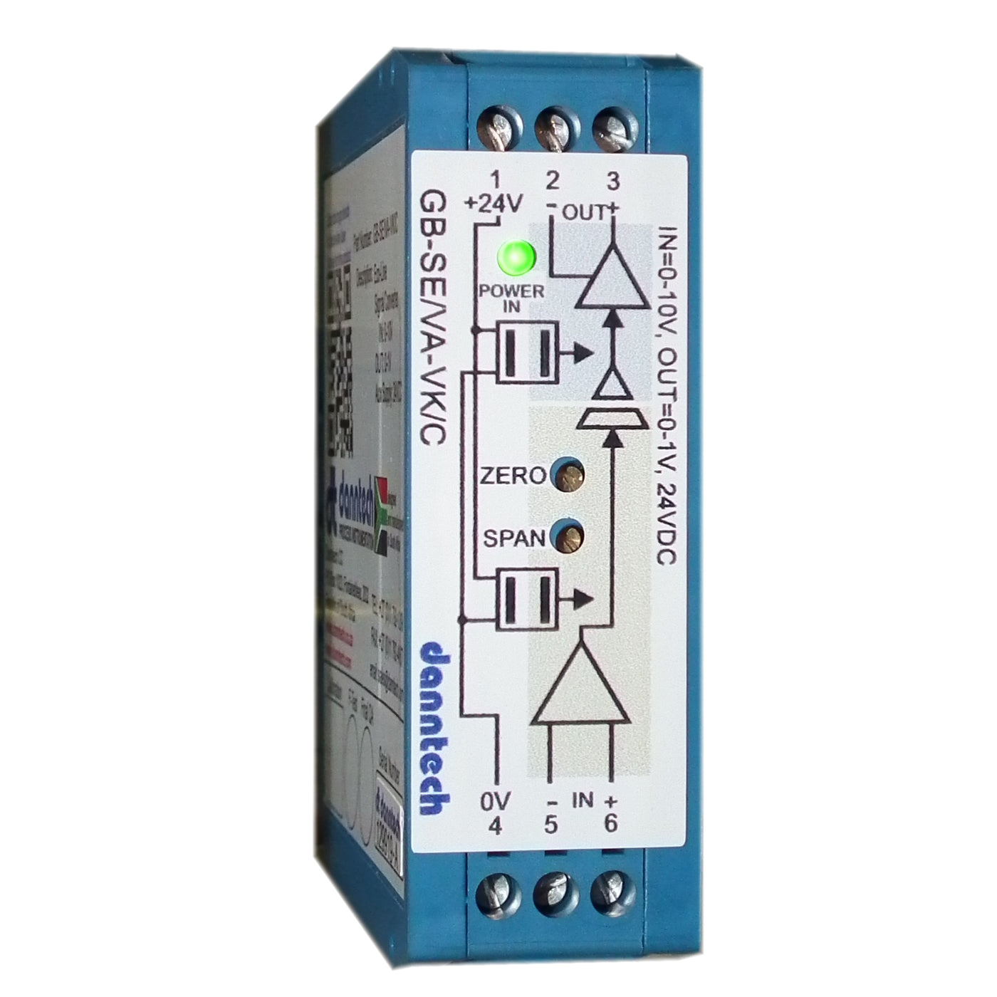
Using miniature DIP switches, a variety of standard inputs and outputs can be selected and with the ‘one button’ calibration, accurate operation in any configuration is assured. Having selected the required input and output ranges, these can be adjusted to be anything within the selected range using the ‘one button’ calibration.
For example, with a 0 to 100 mV input and ±10V output selected, one can calibrate the device to have say 0 to 60 mV input where 30 mV input gives an output of 0 V, 60 mV an output of +6 V and for 0 mV input and output of – 6 V. Output inversion is also easily accommodated.
The Zero and Span trimpots can be disabled or switched to a wider adjustment range using the DIP switches. Filtering is also DIP switch selectable in four ranges up to 60 seconds.
We can also make firmware changes if you have a special application that we have not catered for.

- Standard input and output signal ranges 4-20 mA and 0-10V.
- Input ranges, from 50 mV to 100 V, 1 mA up to 10 A DC.
- Output ranges, from 0-1 V to ±10 V (0 to 100 mV on request), up to 22 mA.
- Bipolar input and output configurations.
- Customised input and output ranges on request.
- Selectable filtering options up to 60 seconds.
- Zero and span trimpots can be locked or disabled using a DIP switch.
- Wide or normal zero and span adjustment selection using a DIP switch.
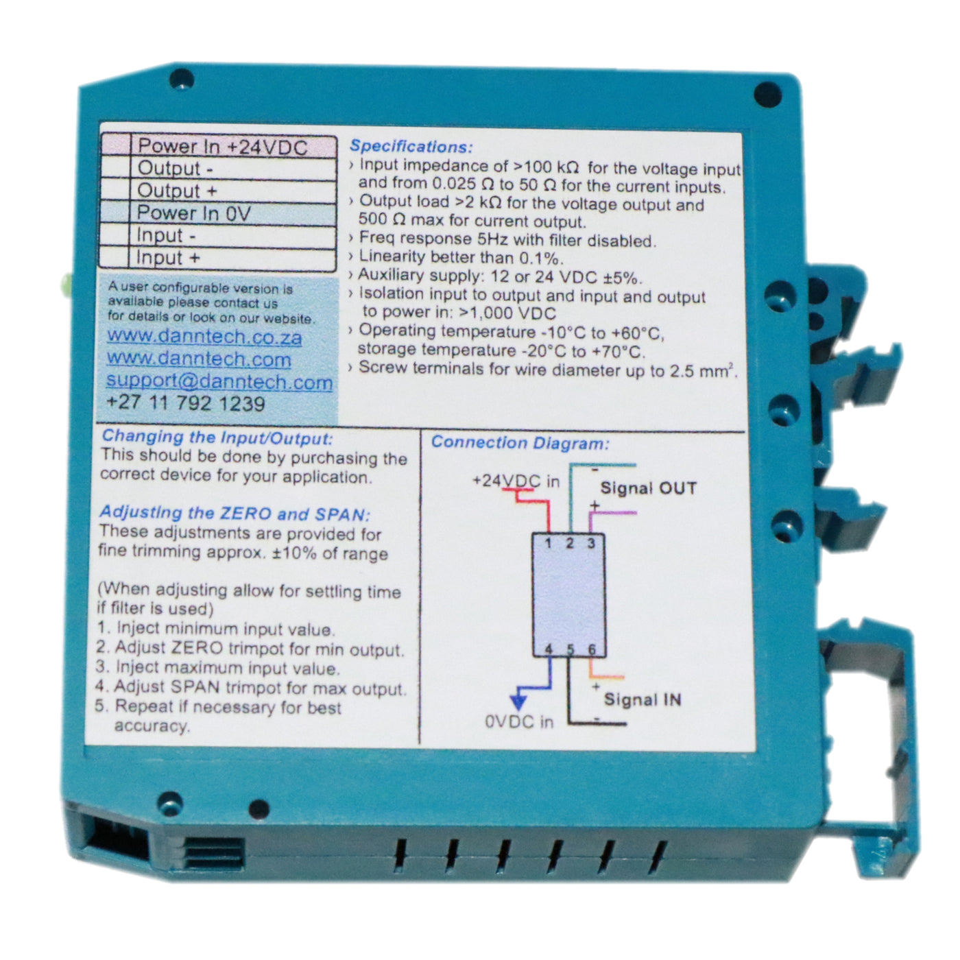
- Input impedance of >100 kΩ for the voltage input and 50 Ω for the current input models.
- Maximum input signals of 100 V for voltage input and 10 A for the current input.
- Output load >2 kS for the voltage output and 500 S maximum for the current output.
- Step response approximately 200 ms.
- Linearity better than 0.1% of full scale.
- Auxiliary supply 24 VDC or 12 VDC ±5%.
- Isolation between input, output and auxiliary power supply 1,000 VDC.
- Operating temperature -10°C to 70°C.
- 24 hour operational burn-in for every device.
- Calibration sheet provided for each unit manufactured.
- DIN rail mounting with dimensions 25 x 80 x 85 mm (W x H x D).
- Signal conversion, amplification and isolation.
- Elimination of the effects of ground loops from distributed process signals.
- Protection of measurement signals against interference such as generated by motors, contactors and power line surges for non-isolated devices and PLC inputs.
- Process signal amplification in situations where the line impedance is too great to effectively drive the required instrumentation.